How To Achieve High Precision Axle Weighing On Single Deck Weighbridges
This Technical Insight focuses on understanding the specifications required to achieve high precision axle weighing on single deck platforms of a range of multi axle horse trailer combinations (“Trucks’).
I. WEIGHBRIDGE DECKS THAT ENABLE AXLE WEIGHING
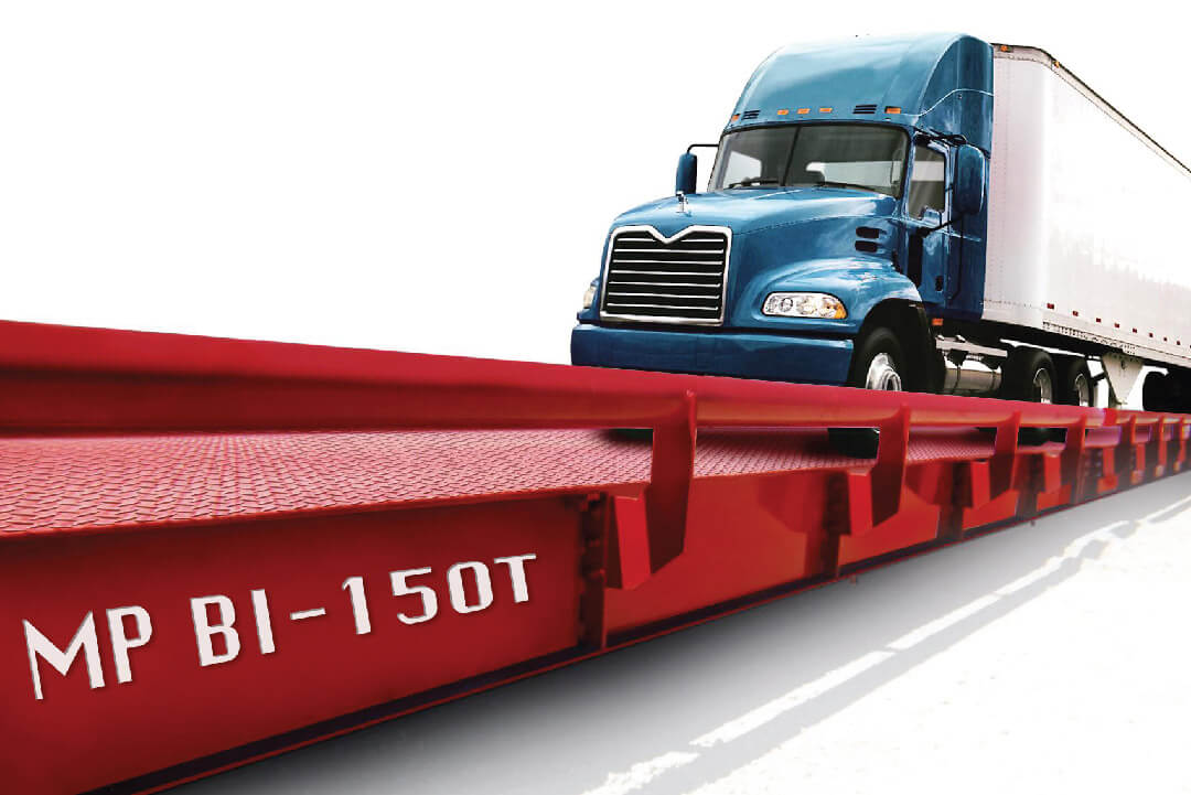
The most common and the most expensive weighing platform that enables axle weights as well as total weights to be generated for Trucks is the multi deck weighbridge. Standard multi decks have four platforms providing total weight in one direction and total weight and axle weights in the other direction.
In addition to the standard four deck multi deck there is also a truly bi-directional five deck multi deck called the Sasco MP BI-150T which enables both total weight and axle weights to be obtained in both directions.
Multi deck weighbridges are essential 4-5 standard weighbridges combined into one system and produce the required weighing results without any complex algorithms being required.
This Technical Insight focuses on the other more cost-effective weighing decks that can provide axle weighing using algorithms, and there are essentially two types:
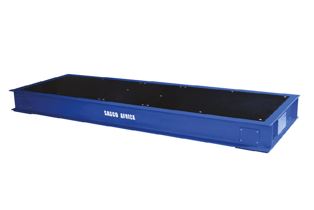
Axle Weigher Platform, with typical dimensions of 3.2m by 0.76m (“Axle Weighers”)
Single deck weighbridge, with typical dimensions of 3.0m by 24m (“Standard Weighbridges”)
II. HIGH PRECISION WEIGHING ON AXLE WEIGHERS
Prior to the revolutionary advancements in instrumentation, digitisation and software, Axle Weighers operated with the Truck moving forward stopping, weighing and axle, and then advancing to weigh the next axle.
Because this type of instrumentation is redundant, and this Technical Insight will focus only on Axle Weighers operating as “weigh-in-motion” (“WIM Systems”). “WIM” refers to a weighing process under which the Truck drives forward at a continuous speed of 3-5 kmph stopping only after all the axles have been weighed.
A. Standard of Civil Works
Accurate results from a WIM System requires accurate civil works. Inaccurate civil works therefore negatively impacts axle weighing accuracy. WIMs must be mounted flush in the ground, with level approaches on both the inbound and out bound of ideally 15m in length either side. Tolerances on the approaches must be to within 5-10mm.
B. Indicator Requirements
WIM Systems require a specialised indicator (such as the Sasco SW 2000) with the following minimum technical specifications:
- A very high sampling speed so that a high volume of readings can be obtained from each load cell per second.
- An inbuilt axle weighing algorithm (“Indicator Algorithm”) capable of computing the accurate axle weight from the series of raw data sampled from the load cells by the indicator.

Sasco SW2000 WIM indicator
C. Generation of Axle Weighing Data
The Indicator Algorithm takes the raw weighing data sampled and computes the “Peak Axle Load” and then deducts from this the “Pre-Weighing Weight” and thereby generates a value for the axle weight. Because the WIM System is only 0.76m long, there can only ever be one axle at a time on the deck so the “Pre-Weighing Weight” in the case of each weighing should be zero.
Note: Because the “Pre-Weighing Weight” is zero, the only error that can arise relates to the accuracy of “Peak Axle Load” as determined by the Indicator Algorithm.
D. Software Data Formulation
The WIM indicator is connected to a computer, on which will be loaded software (such as Sasco ProWeigh+) that is capable, either automatically via unmanned operations or through inputs by a human operator to determine the:
- Truck registration and type
- Axle groupings and permissible axle weights per group
.. and then after taking the weights generated by the WIM indicator:
- Placing these actual weights into the correct axle groups
- Determining the total weight
- Generating a weighing ticket or electronic transmission of a weighing data into an ERP system.
Note: It is important to stress that the software does not do any manipulation or interpretation of the weighing data. All this is done by the Indicator Algorithm which generates the axle weight per axle.
E. Proven Accuracy
Field tests have shown that WIM Systems installed and operated correctly, are capable of consistently producing accuracy levels of:
- >99.0% on total weight
- >98.0 % per axle group
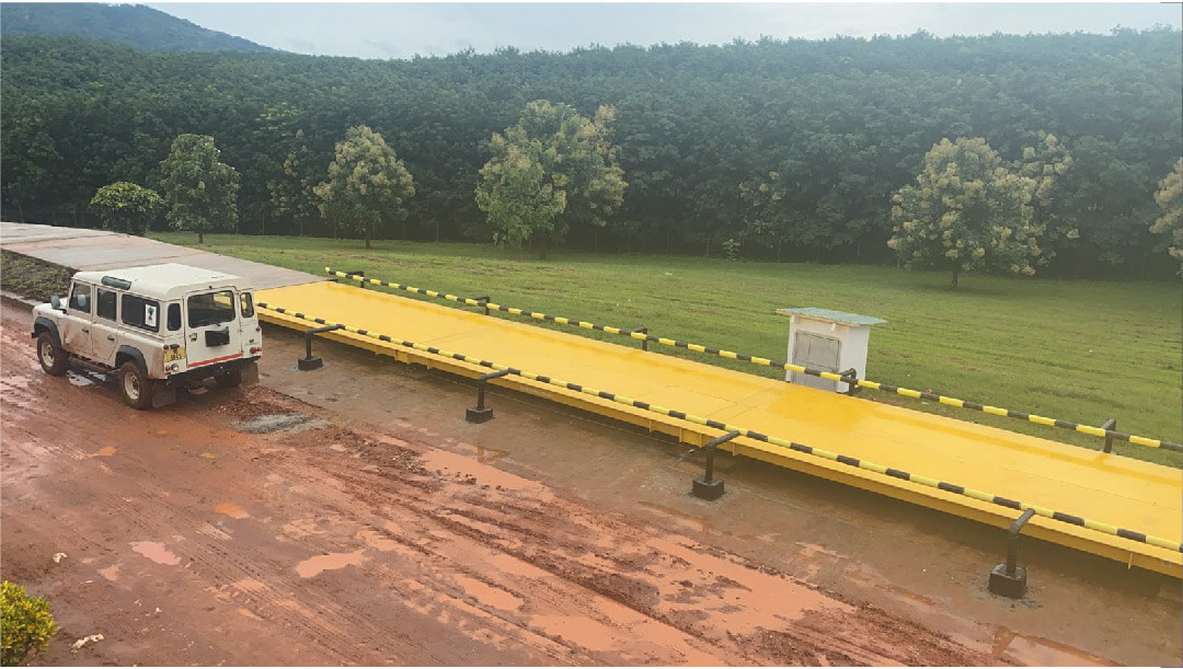
III. HIGH PRECISION AXLE WEIGHING ON STANDARD WEIGHBRIDGES
Advancements in both indicator sampling rates, digitisation and processing power has now made it possible to deliver high precision axle weighing on standard weighbridge decks ( “AW Weighbridges”).
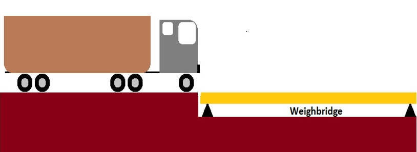
The basic operation entails the truck passing over a level approach onto the weighbridge at a speed of 3-5kmph and stopping once the whole truck is on the weighbridge. The weighing process then takes place from which is generated (a) a total weight and (b) individual axle weights.
A. Standard of Civil Works
Accurate results from AW Weighbridges requires accurate civil works. Inaccurate civil works therefore negatively impacts axle weighing accuracy. The standard of civil works required on AW Weighbridges is therefore higher than that on a straight-forward standard weighbridge providing just total weight.
Irrespective of whether flush mounted or mounted above ground, the weighbridge must be level to within a tolerance of 20mm over its length and 5mm across its width. The inbound approaches to the weighbridge must be at least 15m in length and level to within 5-10mm.
B. Indicator Requirements
Due to the 24m length of a weighbridge, the high number of load cells and the fact that the Pre-Weighing Weight is only zero on the first axle group (becoming a rising value as successive axles move onto the weighbridge) the indicator used for axle weighing (“AW Indicator”) must meet the following minimum specifications:
- A very high sampling speed so that a high volume of readings can be obtained from each load cell per second.
- Inbuilt diagnostics capable of monitoring the operating status of each load cell.
- An inbuilt axle weighing algorithm (“Indicator Algorithm”) capable of computing the accurate axle weight from the series of raw load cell data sampled by the indicator.
- Inbuilt speed and direction algorithm (“Speed Algorithm”) which determines for each weighing the direction of the travel and the truck speed.
- Inbuilt speed compensation adjustment, generated by the Speed Algorithm whereby initial results computed by the Indicator Algorithm are moderated for significant speed deviations.
- A Fine-Tuning Option, allowing at the time of installation, micro amendments to be made by the weighbridge installer to the Indicator Algorithm to accommodate site specific factors
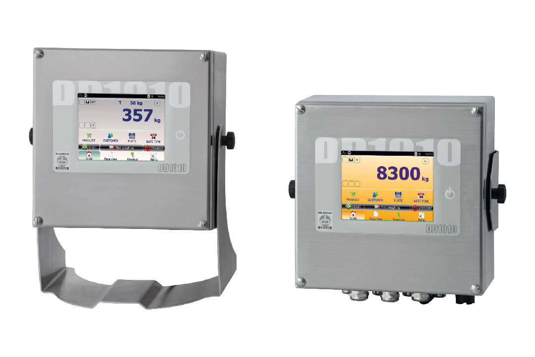
Axle weighing enabled Sasco DD1010 indicator
C. Generation of Axle Weighing Data
On AW Weighbridges, axle weights are generated in much the same way as on the WIM System in that the results are computed by the indicator using the Indicator Algorithm in the indicator (“AW Indicator”).
However, the fact that a weighbridge is 24m long, has multiple load cells and the “Pre-Weighing Weight” is only zero at the time that the first truck axle moves onto the weighbridge, the generation of accurate axle weighing results requires that a more complex set of calculations be performed by the indicator and therefore the specifications must be that much higher.
Using the Sasco DD1010 indicator loaded with Sasco axle firmware, as a specific example:
- As the truck moves onto the weighbridge the indicator will sample each left and right pair of load cells raw data at a rate of at least 20 times per second.
- The Indicator Algorithm will then generate a set of interim axle weights adjusted by any required compensations determined by the Speed Algorithm (“Interim Axle Weights”).
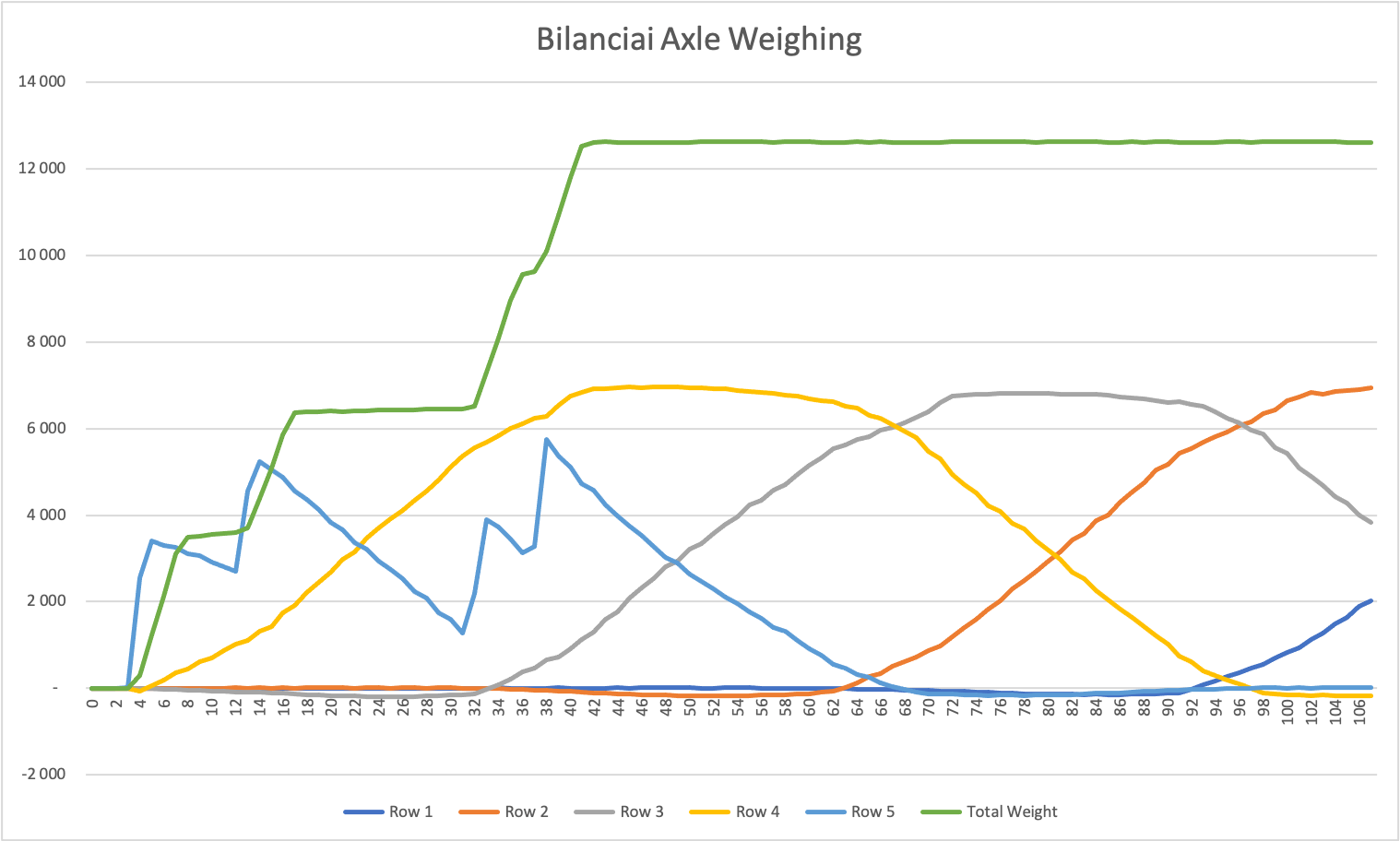
Actual Results on Sasco Weighbridge: 8 Load Cell AW Weighbridge, load cell sampling in L+R pairs, .Indicator sampling speed moderate, truck speed 5 kmph
- The total weight of the truck is then determined by the indicator in the normal way once stationary (“Total Weight”).
- The indicator will then compare the Total Weight to the sum of the Interim Axle Weights and will then proportionally adjust the Interim Axle Weights so that the sum of the Interim axle Weight equals the total weight (“Final Axle Weights”).
D. Software Data Formulation
The AW Indicator is connected to a computer, on which will be loaded software (such as Sasco ProWeigh+) that is capable, either automatically via unmanned operations or through inputs by a human operator, of determining the:
- The truck registration and type of truck
- Axle groupings and permissible axle weights per groupings
.. and then taking the weights generated by the AW Indicator:
- Placing these actual weights into the correct axle groups
- Determining the total weight
- Generating a weighing ticket or electronic transmission of a weighing data into an ERP system.
Note: Again, it is important to stress that the software does not do any manipulation or interpretation of the weighing data. All this is done by the axle weighing algorithm which generates the axle weight per axle.
E. Proven Accuracy
Field tests have shown that AW Weighbridge’s installed and operated correctly, are capable of consistently producing accuracy levels of:
- >99.8% on total weight
- >98.0 % per axle group
IV. UNRELIABLE AND INACCURATE AXLE WEIGHING COMPUTATION METHODS
Most indicators used on standard weighbridges are not axle weighing capable (“ Basic Indicators”). To avoid upgrading to axle weighing capable indicators, a variety of “band aid solutions” using PC based software have been written. This software is simplistic and seeks to:
- Take the “spike weights” that are recorded when a truck drives onto a weighbridge
- Extracting this series of data from the Basic Indicator, and
- Through deducting the value of each successive increasing “weight spike” from the previous values, arriving at axle weights.
This computation method is notoriously unreliable for a variety of reasons:
- Most Basic Indicators do not have high enough sample speeds in the first place so the “weight spikes” often are not capable of being sampled sampled from the point of peak load.
- Each “weight spike” is a single value transmitted from the Basic Indicator to the PC (unlike with an Indicator Algorithm where raw data is received from each load cell, filtered and then a computation executed to arrive at a Peak Axle Load).
- There is no adjustment made for the truck speed.
- There is often no alignment of the total weight to the computed axle weights.
Accordingly, while the first axle weight might be moderately accurate as the starting weight is zero, it is found that as additional truck axles move onto the weighbridge the level of inaccuracy increases, with the results for axles 4-5 onwards are often lost.
The following graph clearly illustrates the issue:
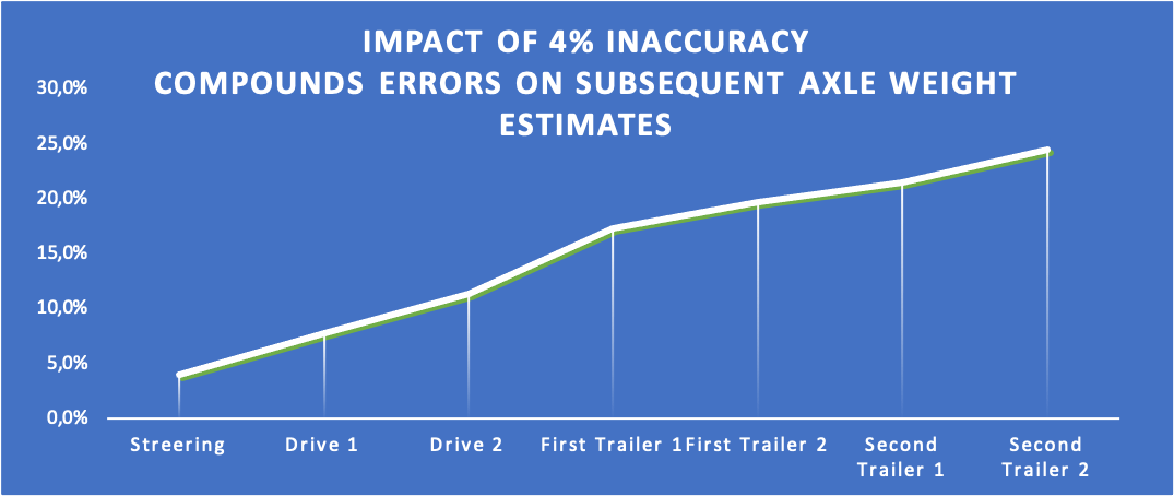
Traffic Regulations allow for a 5% margin for error. “Band aid solutions” offering accuracy of 4% might sound acceptable and are on the first axle group but the compounding error on the cumulative “prior weight estimate” often render the results for subsequent axle inaccurate unacceptable.
Unlike WIM systems, the “Pre-Weighing Weight” is only zero for the first weighing and then aggregates with each successive axle weighing, and with this any errors also compound.
The accuracy of each Peak Load Estimate depends on (a) sample speed (b) sampling the peak (c) multiple load cell data sources (d) speed compensation if required. This error needs to be minimal.
Errors on each “Peak Load Estimate” estimate translates into a compounding error on subsequent “pre weighing estimates”. Since axle weight = Latest Peak Load – Prior Peak Load, errors in estimates get greater for each subsequent axle weighing.
Thanks for reading!
If you have any questions about our weighing solutions or would like a free quote, please click here to contact us. You can also phone the Sasco Support Centre directly on either +27 83 680 0722 or +27 11 746 6000.

Jonathan is a Kenyan born British national who acquired Sasco from Avery Berkel in 2002 and took on the challenge of revitalizing the then ailing company. Jonathan has been CEO of various listed companies, spent 10 years as an investment banker in London, is committed to innovation and in a firm believer in the exceptional growth prospects for Africa over the coming decades.